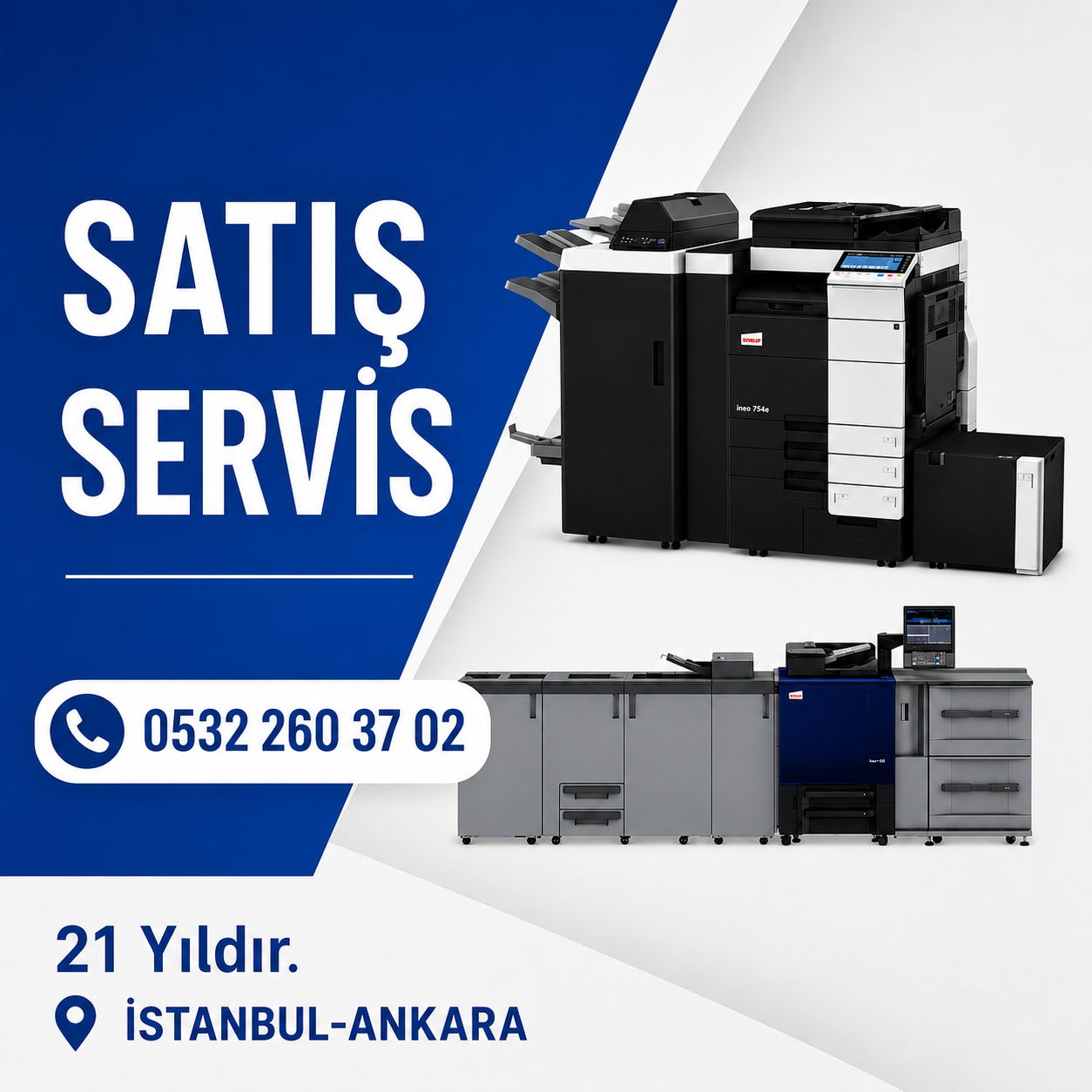

Firmamız, Konica Minolta Bizhub 750i modeli için uzaktan teknik destek, yedek parça temini ve Parts List Service Manual hizmeti sunmaktadır. Müşterilerimize güvenilir ve profesyonel bir hizmet sunmak amacıyla, deneyimli teknisyenlerimizle birlikte çalışmaktayız.

İstanbul, Türkiye'den dünyanın her köşesine; online uzaktan bağlantı ile ücretli teknik servis hizmeti veriyoruz.
We provide paid technical service with online remote connection from Istanbul, Turkey to every corner of the world.
develop İneo+ AccurioPress , develop AccurioPrint Firmware Update, develop firmware update,
driver indir,admin password,admin panel,default admin password,develop yönetici şifresi
develop remote support desktop,
Uzaktan teknik destek hizmetimiz sayesinde, Konica Minolta Bizhub 750i cihazınızda ortaya çıkan herhangi bir sorunu hızlı bir şekilde tespit edip çözebiliriz. Alanında uzman teknisyenlerimiz, uzaktan erişim araçları kullanarak cihazınıza bağlanır ve sorunları etkili bir şekilde giderir. Ayrıca, size yönergeler sağlayarak ve sorularınızı yanıtlayarak tam destek sağlarız.
Yedek parça temini konusunda, orijinal ve yüksek kaliteli Konica Minolta parçaları kullanarak cihazınızın en iyi performansı sergilemesini sağlıyoruz. Parçalarımız uzun ömürlü ve güvenilir olduğu için cihazınızın verimliliğini artırır ve kesintisiz bir çalışma sağlar. İhtiyaç duyduğunuz her an, gerekli yedek parçaları hızlı bir şekilde temin edebiliriz.
Parts List Service Manual'imiz, Konica Minolta Bizhub 750i cihazının parça numaraları, montaj talimatları ve diğer teknik detaylar gibi önemli bilgileri içermektedir. Bu kapsamlı kılavuz, teknik ekibimizin bakım, onarım ve parça değişimi süreçlerinde değerli bir kaynak sağlar.
10.6 CCD Calibration
10.7 LCT Paper Size Setting
Konica Minolta için Uzaktan Teknik Destek, Yedek Parça ve Servis Kılavuzu Hizmetleri
10.9 Data Capture
10.10 Split Line Detect. Setting
10.11 Stamp
10.12 Network Fax Settings
10.13 RX File Change Page Name
10.14 ADF Settings
10.15 User Paper Settings
10.16 Coverage Rate Screen
10.17 JAM Code Display Setting
10.18 Purge Setting
10.19 Import Config. Data
10.19.1 BootUp Screen
10.19.2 Machine Image
10.19.3 Custom Auth. Setting
"Konica Minolta Bizhub 750i Modeli İçin Uzaktan Teknik Destek ve Yedek Parça Hizmeti"
10.20 Install Data
10.21 Local Interface Kit Setting
10.22 CIS Image Adjustment
10.23 Display Eco Index
10.24 Internal Error. Auto Cancel
10.25 Acquiring Settings
10.26 Driver Install
10.27 Application Change Setting
10.28 Custom Pattern
10.29 Maintenance Mode
10.30 Smart Fusing Control
10.31 Cleaning Unit Setting
10.32 Auth. Function Enable
11. Counter
11.1 Outline
11.2 Life
11.3 Service Call
11.4 Section Service Call
11.5 Warning
11.6 Maintenance
11.7 Service Total
11.8 Counter Of Each Mode
11.9 Service Call History (Data)
11.10 ADF Paper Pages
11.11 Paper Jam History
11.12 Fax Connection Error
11.13 ADF Scan Glass Contamin. Counter
konica minolta bizhub 750i service manual,
konica minolta bizhub c224e wireless setup,
konica minolta bizhub reset,
konica minolta bizhub c554,
konica minolta c224e service mode,
konica minolta bizhub factory reset,
konica minolta bizhub 4700p,
konica minolta bizhub c224e,
konica minolta bizhub c754e,
konica minolta bizhub 367 service mode,
konica minolta bizhub 226 reset,
how to reset konica minolta bizhub c360,
konica minolta bizhub c360 factory reset,
konica minolta bizhub 754,
konica minolta bizhub 215 reset,
konica minolta bizhub 283 scanner,
konica minolta c258 service mode,
konica minolta bizhub c224e installation,
konica minolta bizhub c224e network setup,
konica minolta bizhub pro c6500,
konica minolta bizhub c280 error codes,
konica minolta bizhub c280 factory reset,
konica minolta bizhub 164 reset,
konica minolta bizhub c6500,
konica minolta bizhub 4052,
konica minolta bizhub 808,
konica minolta bizhub 950
11.14 Parts Counter (Fixed)
11.14.1 Fixed parts to be counted
11.15 Jam
11.16 Section JAM
11.17 Instantaneous Power Failure
11.18 Detail code history
11.19 Recoverable error counter
12. List Output
12.1 Individual list print output
12.2 Batch list CSV output
13. State Confirmation
13.1 Sensor Check
13.1.1 bizhub 750i
13.1.2 FS-539/FS-539SD
13.1.3 FS-540/FS-540SD
13.2 Table Number
13.3 Level History 1
13.4 Level History 2
13.5 Temp. /Humidity/Atmospheric Press
13.6 CCD Check
13.7 Memory/Storage Adjustment
13.7.1 Memory Check
13.7.2 Compress / Decompression Check
13.7.3 JPEG check
13.7.4 Memory Bus Check
13.7.5 DSC Bus Check
13.7.6 Storage R/W Check
13.7.7 Format
13.8 Memory/Storage Status
13.9 Load Check
13.9.1 Load check list
13.10 Adjustment Data List
13.11 Self-diag. (Full/Individual)
13.11.1 Overview of self-diagnostic function
13.11.2 Self-diag. (Full)
13.11.3 Self-diag. (Individual)
13.12 Media detection
14. Test Mode
14.1 Test Pattern
14.1.1 Gradation Pattern
14.1.2 Halftone Pattern
14.1.3 Lattice Pattern
14.1.4 Solid Pattern
14.1.5 Solid Pattern 2
14.2 Paper Passage Test
14.3 Fax Test
14.4 User Paper 7 Mode
15. ADF
15.1 Original Stop Position
15.2 Registration Loop Adj
15.3 Auto Stop Position Adjustment
15.4 Paper Passage
15.5 Sensor Check
15.6 Original Tray Width
15.7 Read Pos Adj
15.8 FD-Mag. Adj. (F)
15.9 Scanning Light Adjustment
15.10 Mixed original size adjustment
15.11 Home Read Position Adjust
15.12 FD-Mag. Adj. (B)
15.13 Main Scanning Direction Zoom
15.14 Skew Measurement
15.15 ADF automatic Adjustment
15.16 Multi-Feed DetectionAdj
16. FAX
16.1 Outline
16.1.1 PBX operating environment
16.2 Modem/NCU
16.3 Network
16.4 System
16.5 Fax File Format
16.6 Communication
16.7 List Output
16.8 Function Parameter
16.9 Initialization
16.10 Fax Line Std. Setting
16.11 Function parameter list (for all fax lines)
16.11.1 Job setting
16.11.2 Function setting
16.11.3 Report setting
16.11.4 Panel settings
16.12 Function parameter list (for separate line)
16.12.1 Function setting 1
16.12.2 Function setting 2
16.12.3 Function setting 3
16.12.4 Function setting 4
16.12.5 Function setting 5
16.12.6 Fax capacity setting
16.12.7 HP setting
16.13 Recommended Settings for IP Line
17. Finisher
17.1 FS-FN adjustment
17.1.1 Center Staple Position
17.1.2 Half-Fold Position
17.1.3 Punch Centering Fine Adj (for English)
17.1.4 Punch Edge Adj
17.1.5 Punch Regist Loop Size
17.1.6 Punch F. Sensor Intensity Adj
17.1.7 Vertical Punch (Z-Fold) Position (for English)
17.1.8 Horizontal Punch (Z-Fold) Position (for English)
17.1.9 Resist loop size(Z-fold)
17.1.10 Punch Registration Loop Adj
17.1.11 Punch Resist Loop Size (PI)
17.1.12 1st Tri-Fold Adjustment/2nd Tri-Fold Adjustment
17.1.13 1st Z-Fold Position/2nd Z-Fold Position
17.1.14 PI Size Detection
17.1.15 Post Inserter Adjustment
17.1.16 Finisher Components Test Mode
17.1.17 Paper Alignment Guides W. Adj
17.1.18 ZFold1st Fold Loop Size
17.1.19 ZFold2nd Fold Loop Size
17.1.20 ZFold2nd Fold Speed
17.1.21 ZFold Adjust Custom
17.2 Max Staple Limit Setting
17.3 Punch Option Setting
17.4 Max. # of Folded Sheets Setting
17.5 Tri-Fold Output Setting
17.6 Job Separator
17.7 Center Staple Output Setting
18. Network Settings
18.1 2nd Network Setting
18.2 Remote Service Setting
18.2.1 Function Setting
18.2.2 Proxy Server Setting
18.2.3 Maintenance Setting
18.2.4 XMPP Settings
18.2.5 Always Connection Setting
18.3 Port Settings
18.4 MTU Param. set
19. Machine Update Setting
19.1 Internet ISW
19.1.1 Internet ISW Set
19.1.2 HTTP Setting
19.1.3 FTP Setting
19.1.4 Forwarding Access Setting
19.1.5 Download
19.1.6 Update Start Time Settings
19.2 Machine Auto Update setting
19.2.1 Auto Update setting
19.2.2 Relay server setting
19.2.3 Transmission log Update
19.2.4 Transmission Server Log
19.2.5 Update Log Display
19.2.6 Relay Server Log Confirmation
19.2.7 Manually Update
19.2.8 Machine Import setting
19.2.9 Machine Export setting
19.2.10 Machine Update Password
19.3 Firmware Update
19.4 Firmware Rollback
19.5 Copy Network Settings
19.5.1 Outline
19.5.2 Environmental preparations
19.5.3 Deliver/setting procedure
19.6 OSS Update
J) BILLING SETTING/ENHANCED SECURITY/DEBUG SETTINGS
1. BILLING SETTING
1.1 Outline
1.2 Counter Setting
1.2.1 Total Counter Mode
1.2.2 Large Size Counter Mode
1.2.3 Banner Paper Counter Mode
1.2.4 Banner Counter Double Count Mode
1.2.5 Count by the combination of each setting
1.3 Management Function Choice
1.3.1 Key counter only
1.3.2 Management Device 2
1.3.3 Vendor 2
1.3.4 Key Counter IF Vendor
1.4 Authentication Device 2
1.4.1 Installation procedures of authentication unit
1.5 Setting items that automatically change the setting values
1.5.1 When the vendor2 is mounted
1.5.2 When the key counter IF vendor is mounted
1.5.3 When the management device 2 is mounted
1.5.4 When the authentication device 2 is mounted
1.6 Coverage Rate Clear
1.7 License Management
1.7.1 Activation
1.7.2 Deactivation
1.7.3 Repair
1.7.4 Initialize
1.7.5 Request Code
1.7.6 List
1.7.7 Function List
1.8 Manage OpenAPI Authentication
1.9 WebDAV Server Setting
1.10 Coverage Counter Setting
1.11 Print Counter Clear
1.12 Coverage Counter Detail
2. ENHANCED SECURITY
2.1 Outline
2.2 CE Password
2.3 Administrator Password
2.4 Administrator Feature Level
2.5 CE Authentication
2.6 Life Stop Setting
2.7 Memory Data Backup
2.8 operation Ban release time
2.9 Administrator unlocking
2.10 Engine FW DipSW
2.10.1 Details of Each Function
2.11 Engine Data Backup
2.12 Storage Data Backup
2.13 Migration data backup
2.14 Data Backup
2.14.1 Client Function
2.14.2 Server Function
2.15 ADF Data Backup
2.16 Customer Type
2.17 TPM Setting
2.18 FWCert. Settings
3. DEBUG SETTINGS
3.1 Outline
3.2 Debug Log Output
3.3 Acquiring Mode
3.4 TX Debug Log Settings
3.5 Remote Log Retrieval
3.6 Remote Log Server Settings
3.7 Enable Core Dump
3.8 USB Password
3.9 Other
3.9.1 Screen Capture
3.9.2 Panel Operation Playback
3.10 Operation of the debug log function
3.10.1 Advance preparation
3.10.2 Basic mode
3.10.3 Enhance mode
K) FIRMWARE
1. Overview
2. USB memory
2.1 Preparation
2.2 Rewriting of Firmware
2.3 Action when data transfer fails
3. Internet ISW
3.1 Service environment
3.2 Preparation
3.2.1 Making the firmware data
3.2.2 Internet ISW Set
3.3 Rewriting of Firmware
4. Auto Update setting
4.1 Service environment
4.2 Preparation
4.3 Rewriting of Firmware
5. How to install the i-Option data
5.1 Available function for i-Option
5.2 LK-107/LK-108 font data installation procedure
6. Creating back up files when updating firmware
L) TROUBLESHOOTING
1. JAM CODE
1.1 JAM display
1.2 Initial check items
1.3 List of the JAM code
1.4 JAM that do not display the JAM code
1.5 1#-##
1.5.1 10-01, 10-02, 10-04, 10-40
1.5.2 11-01, 11-02, 11-04, 11-05, 11-40
1.5.3 12-01, 12-05, 12-40
1.5.4 13-05, 13-40
1.5.5 14-05, 14-40
1.5.6 15-01, 15-40
1.5.7 17-20
1.5.8 17-30, 17-31
1.5.9 17-40, 17-41
1.6 2#-##
1.6.1 20-01, 20-02, 20-04
1.7 3#-##
1.7.1 30-03
1.7.2 32-01, 32-05, 32-06, 32-30
1.8 6#-##
1.8.1 66-02
1.8.2 66-03, 66-13, 66-23, 66-33
1.8.3 66-04, 66-14
1.8.4 66-05, 66-06
1.8.5 66-07
1.8.6 66-08
1.8.7 66-54
1.9 7#-##
1.9.1 72-11
1.9.2 72-14
1.9.3 72-15
1.9.4 72-16
1.9.5 72-17
1.9.6 72-18
1.9.7 72-19
1.9.8 72-21
1.9.9 72-22
1.9.10 72-23
1.9.11 72-25, 72-26
1.9.12 72-31, 72-34
1.9.13 72-35
1.9.14 72-40, 72-41
1.9.15 72-43
1.9.16 72-49
1.9.17 72-50
1.9.18 72-51
1.9.19 72-75
1.9.20 72-76
1.9.21 72-77
1.9.22 72-81
1.9.23 72-84
1.9.24 72-85
1.9.25 72-86
1.9.26 72-87
1.9.27 75-42
1.9.28 75-43
1.10 9#-##
1.10.1 92-01, 92-02, 92-04, 92-40
1.10.2 93-10
1.10.3 99-01
1.10.4 99-02
1.10.5 99-03
1.10.6 99-04
1.10.7 99-05
1.10.8 99-06
1.10.9 99-07
1.10.10 99-08
1.10.11 99-09
1.10.12 99-10
1.10.13 99-11
1.10.14 99-12
1.10.15 99-14
1.10.16 99-15
1.11 Sensor layout
1.11.1 bizhub 750i
1.11.2 DF-713
1.11.3 LU-205/LU-303
1.11.4 FS-539/FS-539SD/PK-524/RU-519
1.11.5 FS-540/FS-540SD/PK-526/PI-507/ZU-609/RU-519
1.11.6 JS-602
2. MALFUNCTION CODE
2.1 Display procedure
2.2 List of the malfunction code
2.3 S-1
2.4 S-2
2.5 D-1
2.6 D-3
2.7 P-5, P-28
2.8 P-9
2.9 P-27
2.10 P-33
2.11 P-34
2.12 P-35
2.13 P-36
2.14 P-37
2.15 P-38
2.16 P-39
2.17 P-40
2.18 P-41
2.19 P-42
2.20 P-43
3. TROUBLE CODE
3.1 Overview of trouble code
3.2 Overview of troubleshooting procedure
3.2.1 Troubleshooting procedure
3.3 Trouble resetting procedure
3.3.1 Trouble resetting procedure by Trouble Reset key
3.3.2 Trouble resetting procedure by the auto cancel function
3.3.3 Trouble resetting procedure by remote operation
3.4 Nonvolatile memory clear function
3.4.1 Data to be cleared by the nonvolatile memory clear function
3.4.2 Start and execution procedure
3.5 Trouble isolation function
3.6 List of the trouble code
3.7 C0###
3.7.1 C0002
3.7.2 C0104, C0105
3.7.3 C0107
3.7.4 C0202
3.7.5 C0204
3.7.6 C0206
3.7.7 C0208
3.7.8 C0211
3.7.9 C0216
3.8 C1###
3.8.1 C1003, C1013
3.8.2 C1004, C1014
3.8.3 C1007, C1017
3.8.4 C1081, C1082
3.8.5 C1102
3.8.6 C1103
3.8.7 C1104
3.8.8 C1105
3.8.9 C1106
3.8.10 C1109
3.8.11 C1112
3.8.12 C1113
3.8.13 C1114
3.8.14 C1115
3.8.15 C1124
3.8.16 C1125
3.8.17 C1127
3.8.18 C1130
3.8.19 C1131
3.8.20 C1132
3.8.21 C1133
3.8.22 C1140
3.8.23 C1141
3.8.24 C1142
3.8.25 C1143
3.8.26 C1144
3.8.27 C1145
3.8.28 C1146
3.8.29 C1152
3.8.30 C1156
3.8.31 C1184
3.8.32 C1195
3.8.33 C1196
3.8.34 C1197
3.8.35 C11A2
3.8.36 C11C5
3.8.37 C11E1
3.8.38 C11E2
3.8.39 C1403
3.8.40 C1404
3.9 C2###
3.9.1 C2204
3.9.2 C2350
3.9.3 C2355
3.9.4 C2357
3.9.5 C2414
3.9.6 C2557
3.9.7 C2558
3.9.8 C255C
3.9.9 C2564
3.9.10 C2650
3.9.11 C2A14
3.9.12 C2A24
3.10 C3###
3.10.1 C3101, C3103
3.10.2 C3104
3.10.3 C3201, C3202
3.10.4 C3203
3.10.5 C3302
3.10.6 C3306
3.10.7 C3307
3.10.8 C3425
3.10.9 C3722, C3725, C3726
3.10.10 C3737
3.10.11 C3825, C3826
3.10.12 C3922, C3925, C3926
3.10.13 C392B
3.11 C4###
3.11.1 C40A2, C40A3, C40A4, C40A5, C40A6, C40C3, C40C5
3.11.2 C4101
3.11.3 C4501
3.12 C5###
3.12.1 C5102, C5103
3.12.2 C5351
3.12.3 C5355
3.12.4 C5356
3.12.5 C5358
3.12.6 C5360
3.12.7 C5361
3.12.8 C5362
3.12.9 C5370
3.12.10 C5372
3.12.11 C5601
3.12.12 C5603
3.12.13 C5605, C5606
3.12.14 C5610
3.12.15 C5620
3.13 C6###
3.13.1 C6001
3.13.2 C6002
3.13.3 C6102, C6103
3.13.4 C6104, C6105
3.13.5 C6704
3.13.6 C6751
3.13.7 C6752
3.13.8 C6753
3.13.9 C6754, C6755
3.13.10 C6756
3.13.11 C6901, C6902, C6903, C6911, C6912, C6913
3.13.12 C6F01, C6F02, C6F03, C6F04, C6F05, C6F06, C6F07, C6F08, C6F09, C6F0A, C6FDC, C6FDD
3.14 C7###
3.14.1 C7106
3.14.2 C7107
3.14.3 C7111
3.14.4 C7112
3.14.5 C7132
3.14.6 C7137
3.14.7 C7139
3.14.8 C7141
3.14.9 C7160
3.14.10 C7162
3.14.11 C7163
3.14.12 C7164
3.14.13 C7202
3.14.14 C7206
3.14.15 C7241
3.14.16 C7242
3.14.17 C7243
3.14.18 C7251
3.14.19 C7301
3.14.20 C7302
3.14.21 C7304
3.14.22 C7305
3.14.23 C7310
3.14.24 C7311
3.14.25 C7312
3.14.26 C7313
3.14.27 C7314
3.14.28 C7315
3.14.29 C7317
3.14.30 C7318
3.14.31 C7319
3.14.32 C7401
3.14.33 C7402
3.14.34 C7501
3.14.35 C7502
3.14.36 C7601
3.14.37 C7604
3.14.38 C7605
3.14.39 C7606
3.14.40 C7607
3.14.41 C760A
3.14.42 C760B
3.14.43 C760C
3.14.44 C760D
3.14.45 C760E
3.14.46 C760F
3.14.47 C7610
3.14.48 C7622
3.14.49 C7624
3.14.50 C7631
3.14.51 C7633
3.15 C8###
3.15.1 C8103
3.15.2 C8106
3.15.3 C8107
3.15.4 C8302
3.15.5 C8401
3.15.6 C8402
3.16 C9###
3.16.1 C9401, C9402
3.16.2 C9403, C9404
3.16.3 C9701
3.16.4 C9702
3.17 CA###
3.17.1 CA051, CA052, CA053
3.18 CB###
3.19 CC###
3.19.1 CC002
3.19.2 CC151, CC152
3.19.3 CC155
3.19.4 CC156
3.19.5 CC159, CC15A
3.19.6 CC15B
3.19.7 CC15C
3.19.8 CC163
3.19.9 CC164
3.19.10 CC170, CC171, CC172, CC173, CC174, CC180, CC181, CC182, CC183, CC184, CC185, CC186
3.19.11 CC190
3.19.12 CC191
3.19.13 CC211
3.19.14 CC212
3.19.15 CC213
3.19.16 CC214
3.19.17 CC216
3.19.18 CC301
3.19.19 CC302
3.19.20 CCC00
3.20 CD###
3.20.1 CD002
3.20.2 CD004, CD00F, CD020
3.20.3 CD010
3.20.4 CD011
3.20.5 CD012
3.20.6 CD030
3.20.7 CD041, CD042, CD043, CD044, CD045, CD046
3.20.8 CD047, CD048, CD049, CD04A, CD04B
3.20.9 CD050
3.20.10 CD072
3.20.11 CD073
3.20.12 CD110
3.20.13 CD201, CD202, CD203
3.20.14 CD211, CD212
3.20.15 CD241, CD242
3.20.16 CD261
3.20.17 CD262
3.20.18 CD2D1
3.20.19 CD3##
3.20.20 CD313
3.20.21 CD38E
3.20.22 CD390
3.20.23 CD391
3.20.24 CD392
3.20.25 CD3B1, CD3B3, CD3B4, CD3B5
3.20.26 CD3C0
3.20.27 CD401, CD402, CD403, CD404, CD405, CD406, CD407, CD411, CD412, CD413
3.20.28 CD601, CD602, CD603
3.20.29 CD701, CD702, CD703
3.20.30 CD704
3.20.31 CDC##
3.20.32 CDF50, CDF70, CDFA0
3.20.33 CDF51, CDF71, CDFA1
3.21 CE###
3.21.1 CE001, CE003, CE004, CE005, CE006, CE007, CE009
3.21.2 CE002
3.21.3 CE012
3.21.4 CE013
3.21.5 CE014
3.21.6 CE015
3.21.7 CE101
3.21.8 CE201
3.21.9 CE202
3.21.10 CE203
3.21.11 CE204
3.21.12 CE301, CE302, CE303, CE304, CE305
3.21.13 CE401
3.21.14 CED01
3.21.15 CEEE1, CEEE3
3.21.16 CEEE2
3.22 CF### (Abort code)
3.22.1 CFA##
3.22.2 CFB##
3.22.3 CFC##
3.22.4 CFD##
3.22.5 CFE##
3.22.6 CFF##
4. TROUBLESHOOTING USING SELF-DIAG. (FULL)
4.1 Overview of Self-diag. (Full) function
4.2 Self-diag. (Full) Procedure
4.2.1 Auto Execution of Self-diag. (Full)
4.2.2 Error code resetting procedures
4.3 Error Code List
4.4 E1-1
4.5 E1-2
4.6 E1-3
4.7 E1-4
4.8 E1-5
4.9 E2-1
4.10 E2-2
4.11 E2-3
4.12 E2-4
4.13 E2-5
4.14 E3-1
4.15 E3-2, E3-3
4.16 E4-1, E4-2
4.17 E4-3, E4-4
4.18 E5-1
4.19 E5-2
4.20 E5-3
4.21 E5-4
4.22 E5-5
4.23 E5-6, E5-7, E5-8, E5-9, E5-10
4.24 E5-11
4.25 E5-12
4.26 E6-1, E6-2
4.27 E7-1, E7-2
4.28 E8-1
4.29 E9-1
4.30 E10-1, E10-2
4.31 E11-1, E11-2
4.32 E12-1, E12-2, E12-3, E12-4
5. TROUBLESHOOTING WHEN NG IS DISPLAYED ON THE SELF-DIAG. (INDIVIDUAL)
5.1 I2S check
5.1.1 Troubleshooting when NG is displayed for AUDIO (voice)
5.2 Various USB Check
5.2.1 Troubleshooting when NG is displayed for Keyboard
5.2.2 Troubleshooting when NG is displayed for USB Memory
5.3 CPU board check
5.3.1 Troubleshooting when NG is displayed for Ping Test
6. ERROR CODE FOR THE INTERNET ISW
6.1 Error code list for the Internet ISW
6.2 0x0#
6.3 0x1#
6.4 0x2#
7. CS REMOTE CARE ERROR CODE
7.1 Troubleshooting for CS Remote Care
7.2 CS Remote Care Operation under Enhanced Security Mode
7.3 List of the CS Remote Care error code
7.3.1 When connecting by modem
7.3.2 When connecting by e-mails
7.3.3 When connecting by http
7.3.4 When connecting by Fax modem
8. CS REMOTE ANALYSIS ERROR CODE
8.1 When connecting by SOAP
8.1.1 1###
8.1.2 2###
8.1.3 3###
8.1.4 4###
8.2 When connecting by http
8.2.1 0###
8.2.2 1###
8.2.3 2###
8.2.4 3###
8.2.5 4###
8.2.6 5###
8.2.7 6###
8.2.8 7###
9. FAX TROUBLE CODE
9.1 The error in the transmission/reception system
9.2 B0##
9.3 B11#
9.4 B12#
9.5 B13#
9.6 B14#
9.7 B15#
9.8 B16#
9.9 B17#
9.10 B18#
9.11 B19#
9.12 T0#
9.13 T1#
9.14 T2#
9.15 T3#
9.16 T4#
9.17 T5#
9.18 T6#
9.19 T7#
9.20 T8#
9.21 T9#
9.22 R0#
9.23 R1#
9.24 R2#
9.25 R3#
9.26 R4#
9.27 R5#
9.28 R6#
9.29 R7#
9.30 R8#
9.31 R9#
9.32 Other
10. DIAGNOSTIC CODES
10.1 Outline
10.2 Explanation
10.2.1 The diagnostic code
10.2.2 Information of communication results and conditions
11. NETWORK FAX ERROR CODE
11.1 Error code list of the transmission system
11.2 Error code list of the reception system
11.3 Other
12. OPEN API RELATED TROUBLE
12.1 Outline
12.2 Types of Trouble
12.3 Solution
12.3.1 When using an application
12.3.2 After rewriting the firmware of the machine
13. PANEL BLACKOUT TROUBLE (BOOT DIAGNOSIS FUNCTION)
13.1 Boot diagnosis function
13.1.1 Boot diagnosis sequence
13.1.2 Manual boot diagnosis procedure
13.1.3 Boot diagnosis result list
13.1.4 How to reset the boot diagnosis result
14. TROUBLES THAT DO NOT DISPLAY THE TROUBLE CODE
14.1 Machine is not energized at all (DCPU operation check)
14.2 Fusing heaters do not operate
14.3 Power is not supplied to DF
14.4 Power is not supplied to option
15. OTHER TROUBLE
15.1 Firmware error warning
15.2 Storage lock password error warning
15.3 Progress bar stops halfway when the main power switch is turned on
16. TROUBLESHOOTING OF i-Option
16.1 Structure of license management
16.2 License management information
16.3 Error message
16.3.1 License management error
17. IMAGE QUALITY PROBLEM
17.1 How to read element data
17.1.1 Table Number
17.1.2 Level History 1
17.1.3 Level History 2
17.2 Troubleshooting procedure overview
17.2.1 Test pattern printing
17.3 Corrective action procedure
17.3.1 Skewed image/Image deviation
17.3.2 White line 1, white band 1, black line 1, black band 1
17.3.3 White line 2, white band 2, black line 2, black band 2
17.3.4 Uneven density 1
17.3.5 Uneven density 2
17.3.6 Faint image, low image density (ID lowering)
17.3.7 Gradation reproduction failure
17.3.8 Foggy background
17.3.9 Void areas, White spots
17.3.10 Black spots
17.3.11 Blurred image
17.3.12 Back marking
17.3.13 Blank copy, Black copy
17.3.14 Uneven pitch
17.3.15 Uneven gloss, Rough gloss
17.3.16 Poor fusing performance, Offset
17.3.17 Brush effect, Image bleeding
17.3.18 Blurred fine lines
17.3.19 Moire
17.3.20 Distorted image
17.3.21 ACS malfunction
17.3.22 Abnormal image
18. IC PROTECTOR
18.1 Outline
18.2 IC protector list
18.2.1 bizhub 750i
18.2.2 DF-713
18.2.3 FS-539/FS-539SD
18.2.4 FS-540/FS-540SD
18.2.5 PK-526
18.2.6 PI-507
18.2.7 ZU-609
M) PARTS/CONNECTOR LAYOUT DRAWING
1. PARTS LAYOUT DRAWING
1.1 bizhub 750i
1.1.1 Scanner section
1.1.2 Front side
1.1.3 Back side
1.1.4 Left side
1.1.5 Right side
1.1.6 Manual bypass tray
1.1.7 Tray 1
1.1.8 Tray 2
1.1.9 Tray 3/4
1.1.10 Fusing/paper exit section
1.1.11 Duplex section
1.2 DF-713
1.3 LU-205
1.4 LU-303
1.5 RU-519
1.6 FS-539/FS-539SD
1.7 FS-539SD saddle section
1.8 PK-524
1.9 FS-540/FS-540SD
1.10 FS-540SD saddle section
1.11 PK-526
1.12 ZU-609
1.13 JS-602
1.14 PI-507
1.15 OT-514
1.16 CU-102
1.17 WT-519
2. CONNECTOR LAYOUT DRAWING
2.1 BOARD CONNECTOR LAYOUT DRAWING
2.1.1 bizhub 750i
2.1.2 Tray 3/4
2.1.3 WT-519
2.1.4 DF-713
2.1.5 FS-539/FS-539SD
2.1.6 FS-540/FS-540SD
2.1.7 PK-526
2.1.8 ZU-609
2.1.9 PI-507
2.1.10 FK-514 (line 1/2)
2.1.11 FK-515 (line 3/4)
2.1.12 CU-102
2.1.13 SC-509
2.1.14 EM-908
2.1.15 IM-102
2.2 RELAY CONNECTOR LAYOUT DRAWING
2.2.1 Main body
2.2.2 Tray 3/4
N) TIMING CHART
1. bizhub 750i
1.1 Timing chart when printing
2. LU-205/LU-303
O) WIRING DIAGRAM
1. bizhub 750i
1.1 Main body
2. DF-713
3. LU-205
4. LU-303
5. FS-539/FS-539SD
6. FS-540/FS-540SD
7. PK-526
8. ZU-609
9. PI-507
P THEORY OF OPERATION
1. bizhub 750i
1.1 INTERFACE SECTION
1.1.1 Configuration
1.2 SCANNER SECTION
1.2.1 Configuration
1.2.2 Drive
1.2.3 LED exposure unit
1.2.4 When the power is ON
1.2.5 Control when the Start key is pressed
1.2.6 Original scanning area
1.2.7 Original size detection control
1.3 WRITE SECTION (PH SECTION)
1.3.1 Configuration
1.3.2 Overview
1.3.3 Laser exposure process
1.3.4 Laser emission timing
1.3.5 Laser emission stop
1.3.6 Laser emission area
1.3.7 PH unit temperature detection control
1.3.8 PH window cleaning
1.4 PHOTOCONDUCTOR SECTION
1.4.1 Configuration
1.4.2 Drive
1.4.3 Erase LED control
1.4.4 Photoconductor cleaning
1.4.5 Electrostatic charger control
1.4.6 Charging roller cleaning
1.4.7 Drum unit mounting detection
1.5 DEVELOPING SECTION
1.5.1 Configuration
1.5.2 Drive
1.5.3 Developing unit pressure/releases mechanism
1.5.4 Developer flow
1.5.5 Auto refining developing system
1.5.6 Developing bias
1.5.7 Toner scattering prevention
1.5.8 Developing cooling
1.5.9 Toner density control
1.5.10 Developing unit mounting detection
1.6 TONER SUPPLY SECTION
1.6.1 Configuration
1.6.2 Drive
1.6.3 Toner replenishing overview
1.6.4 Toner replenishing from toner bottle to toner hopper
1.6.5 Toner replenishing from toner hopper to developing unit
1.6.6 Auxiliary toner replenishing control for toner hopper
1.6.7 Auxiliary toner replenishing control for developing unit
1.6.8 Toner spillage prevention shutter
1.6.9 Toner empty detection control
1.7 1ST TRANSFER SECTION
1.7.1 Configuration
1.7.2 Drive
1.7.3 1st transfer roller control
1.7.4 1st transfer control
1.7.5 Transfer belt cleaning
1.7.6 Waste toner spillage prevention shutter
1.7.7 Cleaning blade foreign matter removal control
1.7.8 Transfer belt new article detection
1.8 2ND TRANSFER SECTION
1.8.1 Configuration
1.8.2 Drive
1.8.3 2nd transfer control
1.8.4 Control of toner application to 2nd transfer roller
1.8.5 2nd transfer roller cleaning
1.8.6 Charge neutralization and separation of paper
1.8.7 2nd transfer roller new article detection
1.9 TONER COLLECTING SECTION
1.9.1 Configuration
1.9.2 Waste toner box drive mechanism
1.9.3 Control of waste toner conveyance through waste toner box
1.9.4 Waste toner box drive section rotation detection
1.9.5 Waste toner box-in-position detection
1.9.6 Waste toner box full detection
1.9.7 Waste toner box new article detection
1.9.8 Waste toner spillage prevention shutter
1.10 PAPER FEED SECTION (TRAY 1/2)
1.10.1 Configuration
1.10.2 Drive
1.10.3 Up/down control
1.10.4 Paper feed control
1.10.5 Paper feed retry control
1.10.6 Feed roller speed reduction control
1.10.7 Vertical transport roller speed reduction control
1.10.8 Paper transport control
1.10.9 Downstream exit control during multi-print cycle
1.10.10 Paper size detection control
1.10.11 Regulation of trailing edge of small-sized paper
1.10.12 Remaining paper detection control
1.10.13 Paper feed tray locking mechanism
1.10.14 Roller retract mechanism
1.10.15 Paper feed tray stopper release mechanism
1.11 PAPER FEED SECTION (TRAY 3/4)
1.11.1 Outline
1.12 PAPER FEED SECTION (MANUAL BYPASS TRAY)
1.12.1 Configuration
1.12.2 Drive
1.12.3 Up/down control
1.12.4 Paper feed control
1.12.5 Paper size detection control
1.12.6 Paper empty detection control
1.12.7 Bypass tray pick-up roller retract mechanism
1.13 REGISTRATION SECTION
1.13.1 Configuration
1.13.2 Registration control
1.13.3 Paper trailing edge detection
1.13.4 Automatic detection of paper type
1.14 FUSING SECTION
1.14.1 Configuration
1.14.2 Drive
1.14.3 Fusing speed correction
1.14.4 Fusing pressure/retraction control
1.14.5 Paper separation mechanism
1.14.6 Fusing temperature control
1.14.7 HaCS control
1.14.8 Plain paper fusing temperature control
1.14.9 Smart fusing control
1.14.10 Fusing edge cooling mechanism
1.14.11 Protection from abnormal temperatures
1.14.12 Fusing PPM control
1.14.13 Fusing unit new article detection
1.15 PAPER EXIT/REVERSE SECTION
1.15.1 Configuration
1.15.2 Drive
1.15.3 Transport control
1.16 DUPLEX SECTION
1.16.1 Configuration
1.16.2 Paper transport control
1.16.3 Duplex circulation control
1.17 IMAGE STABILIZATION CONTROL
1.17.1 Overview
1.17.2 Description of control
1.17.3 Control contents
1.17.4 Operation timing
1.17.5 Image stabilization control during SRA3 size printing
1.18 IMAGE PROCESSING
1.18.1 Scanner section image processing block diagram
1.18.2 Write section image processing block diagram
1.19 POWER SUPPLY SECTION
1.19.1 Main power switch
1.19.2 Power key
1.20 FAN CONTROL
1.20.1 Configuration
1.20.2 Control
1.20.3 PH/power supply cooling fan
1.20.4 Transfer belt cleaner cooling fan
1.20.5 Rear side cooling fan
1.20.6 Toner cartridge cooling fan
1.20.7 HaCS power supply cooling fan
1.20.8 Paper cooling fan
1.20.9 Toner suction fan
1.20.10 UFP scavenging fan
1.20.11 DV cooling fan
1.20.12 Fusing edge cooling fan
1.20.13 Machine internal cooling fan
1.21 COUNTER CONTROL
1.21.1 Configuration
1.21.2 Operation
1.22 HEATER
1.22.1 HT-509/MK-734
1.22.2 LU/TK-101
1.23 INDICATOR FUNCTION
1.23.1 Configuration
1.23.2 Control
2. DF-713
2.1 Configuration
2.1.1 Section configuration
2.1.2 Main part configuration
2.2 Outline
2.3 Document feed section
2.3.1 Drive
2.3.2 Document set/empty detection
2.3.3 Document size detection mechanism
2.3.4 Up/down control for the document feed tray
2.3.5 Document feed control
2.3.6 Upper door open/close detection mechanism
2.3.7 Document feed tray open and close detection mechanism
2.3.8 Double feed detection
2.4 Document registration section
2.4.1 Drive
2.4.2 Registration control
2.5 Document reading section
2.5.1 Drive
2.5.2 Document reading transport control
2.5.3 CIS document reading control
2.5.4 Reading speed correction control
2.5.5 Document reading glass contamination prevention control
2.5.6 CIS glass contamination prevention control
2.5.7 Opening and closing guide set detection
2.6 Document exit section
2.6.1 Drive
2.6.2 Document exit mechanism
2.6.3 Faxed document stamp function (SP-501)
2.7 DF open/close detection mechanism
2.8 Cooling inside the unit mechanism
3. PC-417
3.1 Configuration
3.2 Paper path
3.3 Drive
3.3.1 Tray 3
3.3.2 Tray 4
3.3.3 Horizontal transport/Vertical transport
3.4 Up down control
3.4.1 Up operation
3.4.2 Down operation
3.4.3 Operation timing
3.5 Paper feed control
3.5.1 Pick-up control
3.6 Horizontal transport control
3.7 Paper feed retry control
3.8 Paper feed temporary stop control
3.9 Paper size detection control
3.9.1 Paper guide position regulation
3.9.2 Paper size settings
3.10 Remaining paper detection control
3.10.1 Paper near-empty detection
3.10.2 Paper empty detection
3.10.3 Remaining paper level detection
3.10.4 Remaining paper level display
3.11 Roller retract mechanism
3.11.1 Tray 3
3.11.2 Tray 4
3.12 Tray open/close detection mechanism
4. LU-205
4.1 CONFIGURATION
4.1.1 Exterior view
4.1.2 SECTION CONFIGURATION
4.1.3 Main part
4.1.4 Electrical part
4.2 PAPER PATH
4.3 DRIVE
4.3.1 Paper feed transport drive
4.3.2 Paper lift-up drive
4.4 Unit open/close section
4.4.1 Unit lock mechanism
4.4.2 LU door open/close detection mechanism
4.5 Paper storage section
4.5.1 Paper tray lifting mechanism
4.5.2 Paper tray lift-up drive release mechanism
4.5.3 Paper guide plate
4.6 Paper feed/transport section
4.6.1 Paper feed control
4.6.2 Paper transport control
4.6.3 Remaining paper level detection
4.6.4 Paper empty detection
4.6.5 Remaining paper display
5. LU-303
5.1 CONFIGURATION
5.1.1 Exterior view
5.1.2 SECTION CONFIGURATION
5.1.3 Main part
5.1.4 Electrical part
5.2 PAPER PATH
5.3 DRIVE
5.3.1 Paper feed transport drive
5.3.2 Paper lift-up drive
5.4 Unit open/close section
5.4.1 Unit lock mechanism
5.4.2 LU door open/close detection mechanism
5.5 Paper storage section
5.5.1 Paper tray lifting mechanism
5.5.2 Paper tray lift-up drive release mechanism
5.5.3 Paper size detection mechanism
5.6 Paper feed/transport section
5.6.1 Paper feed control
5.6.2 Paper transport control
5.6.3 Remaining paper level detection
5.6.4 Paper empty detection
5.6.5 Remaining paper display
6. OT-514
6.1 Configuration
6.2 Paper cooling mechanism
7. RU-519
7.1 Configuration
7.2 Drive
7.3 Paper transport control
7.4 RU section door open/close detection mechanism
7.5 3rd exit tray full detection mechanism
8. FS-539/FS-539SD/PK-524
8.1 Configuration
8.2 Paper path
8.3 FINISHER SECTION
8.3.1 Door open/close detection mechanism
8.4 TRANSPORT SECTION
8.4.1 Configuration
8.4.2 Drive
8.4.3 Paper path switching mechanism
8.4.4 Receiving roller section up/down function
8.4.5 Buffer control
8.4.6 Sub tray exit mechanism
8.5 ALIGNMENT SECTION
8.5.1 Configuration
8.5.2 Drive
8.5.3 Paper transport control to alignment section
8.5.4 Paper alignment control
8.5.5 Paper exit control
8.6 STAPLER SECTION
8.6.1 Configuration
8.6.2 Drive
8.6.3 Stapler movement control
8.6.4 Manual staple mechanism
8.6.5 Staple control
8.6.6 Staple empty detection control
8.7 OUTPUT TRAY SECTION
8.7.1 Configuration
8.7.2 Drive
8.7.3 Main tray up/down mechanism
8.7.4 Main tray paper level detection control
8.7.5 Main tray position detection mechanism
8.7.6 Tray full detection mechanism
8.8 Saddle section
8.8.1 Configuration
8.8.2 Transport section
8.8.3 Alignment section
8.8.4 Stapler
8.8.5 Folding/Saddle stitching
8.8.6 Tri-folding
8.8.7 Exit section
8.9 PK-524
8.9.1 Configuration
8.9.2 Drive
8.9.3 Skew correction control
8.9.4 Punch control
8.9.5 Puncher up/down status detection configuration
8.9.6 Punch dust box full detection mechanism
8.9.7 Punch dust box installation detection mechanism
9. FS-540/FS-540SD/PK-526/JS-602/PI-507/ZU-609
9.1 CONFIGURATION
9.2 PAPER PATH
9.3 FINISHER SECTION
9.3.1 Door open/close detection mechanism
9.4 TRANSPORT SECTION
9.4.1 Configuration
9.4.2 Drive
9.4.3 Route change gate
9.4.4 Sub tray/JS route change gate
9.4.5 Receiving roller section up/down function
9.4.6 Buffer control
9.4.7 Sub tray output
9.5 ALIGNMENT SECTION
9.5.1 Configuration
9.5.2 Drive
9.5.3 Paper transport control
9.5.4 Paper alignment control
9.5.5 Paper exit control
9.5.6 Stack support plate control
9.6 STAPLER SECTION
9.6.1 Configuration
9.6.2 Drive
9.6.3 Stapler position detection
9.6.4 Manual staple mechanism
9.6.5 Staple control
9.7 OUTPUT TRAY SECTION
9.7.1 Configuration
9.7.2 Drive
9.7.3 Main tray up/down mechanism
9.7.4 Main tray paper detection
9.7.5 Main tray position detection mechanism
9.7.6 Tray full detection mechanism
9.8 SADDLE SECTION
9.8.1 Configuration
9.8.2 Transport section
9.8.3 Alignment section
9.8.4 Stapler
9.8.5 Folding/Saddle stitching
9.8.6 Tri-folding
9.8.7 Exit section
9.9 PK-526
9.9.1 Configuration
9.9.2 Drive
9.9.3 Punch standby position movement control
9.9.4 Punch position correction control
9.9.5 Punch control
9.9.6 Punch dust box control
9.10 ZU-609
9.10.1 Configuration
9.10.2 Drive
9.10.3 1st folding mechanism
9.10.4 2nd folding mechanism
9.10.5 Double-folding mechanism
9.10.6 Transport roller pressure change
9.10.7 Z-fold pressure release mechanism
9.10.8 Z-fold paper detection
9.11 PI-507
9.11.1 Configuration
9.11.2 Drive
9.11.3 Tray lift mechanism
9.11.4 Pick-up mechanism
9.11.5 Separation mechanism
9.11.6 Path switching mechanism
9.11.7 Paper size detection control
9.11.8 Door open/close detection mechanism
9.12 JS-602
9.12.1 Configuration
9.12.2 Drive
9.12.3 Job tray transport mechanism
9.12.4 Door open/close detection mechanism
10. FK-514/FK-515/MK-742
10.1 COMMUNICATION CONTROL
10.1.1 FIF bits of DIS, DTC and DCS
10.1.2 Modem fallback sequence
10.1.3 V8/V34 sequence
10.2 FUNCTION
10.2.1 Telephone function
| Technical | |
| Teknik Destek Verdiğimiz Modeller | 3. TROUBLE CODE 3.1 Overview of trouble code 3.2 Overview of troubleshooting procedure 3.2.1 Troubleshooting procedure 3.3 Trouble resetting procedure 3.3.1 Trouble resetting procedure by Trouble Reset key 3.3.2 Trouble resetting procedure by the auto cancel function 3.3.3 Trouble resetting procedure by remote operation 3.4 Nonvolatile memory clear function 3.4.1 Data to be cleared by the nonvolatile memory clear function 3.4.2 Start and execution procedure 3.5 Trouble isolation function 3.6 List of the trouble code 3.7 C0### 3.7.1 C0002 3.7.2 C0104, C0105 3.7.3 C0107 3.7.4 C0202 3.7.5 C0204 3.7.6 C0206 3.7.7 C0208 3.7.8 C0211 3.7.9 C0216 3.8 C1### 3.8.1 C1003, C1013 3.8.2 C1004, C1014 3.8.3 C1007, C1017 3.8.4 C1081, C1082 3.8.5 C1102 3.8.6 C1103 3.8.7 C1104 3.8.8 C1105 3.8.9 C1106 3.8.10 C1109 3.8.11 C1112 3.8.12 C1113 3.8.13 C1114 3.8.14 C1115 3.8.15 C1124 3.8.16 C1125 3.8.17 C1127 3.8.18 C1130 3.8.19 C1131 3.8.20 C1132 3.8.21 C1133 3.8.22 C1140 3.8.23 C1141 3.8.24 C1142 3.8.25 C1143 3.8.26 C1144 3.8.27 C1145 3.8.28 C1146 3.8.29 C1152 3.8.30 C1156 3.8.31 C1184 3.8.32 C1195 3.8.33 C1196 3.8.34 C1197 3.8.35 C11A2 3.8.36 C11C5 3.8.37 C11E1 3.8.38 C11E2 3.8.39 C1403 3.8.40 C1404 3.9 C2### 3.9.1 C2204 3.9.2 C2350 3.9.3 C2355 3.9.4 C2357 3.9.5 C2414 3.9.6 C2557 3.9.7 C2558 3.9.8 C255C 3.9.9 C2564 3.9.10 C2650 3.9.11 C2A14 3.9.12 C2A24 3.10 C3### 3.10.1 C3101, C3103 3.10.2 C3104 3.10.3 C3201, C3202 3.10.4 C3203 3.10.5 C3302 3.10.6 C3306 3.10.7 C3307 3.10.8 C3425 3.10.9 C3722, C3725, C3726 3.10.10 C3737 3.10.11 C3825, C3826 3.10.12 C3922, C3925, C3926 3.10.13 C392B 3.11 C4### 3.11.1 C40A2, C40A3, C40A4, C40A5, C40A6, C40C3, C40C5 3.11.2 C4101 3.11.3 C4501 3.12 C5### 3.12.1 C5102, C5103 3.12.2 C5351 3.12.3 C5355 3.12.4 C5356 3.12.5 C5358 3.12.6 C5360 3.12.7 C5361 3.12.8 C5362 3.12.9 C5370 3.12.10 C5372 3.12.11 C5601 3.12.12 C5603 3.12.13 C5605, C5606 3.12.14 C5610 3.12.15 C5620 3.13 C6### 3.13.1 C6001 3.13.2 C6002 3.13.3 C6102, C6103 3.13.4 C6104, C6105 3.13.5 C6704 3.13.6 C6751 3.13.7 C6752 3.13.8 C6753 3.13.9 C6754, C6755 3.13.10 C6756 3.13.11 C6901, C6902, C6903, C6911, C6912, C6913 3.13.12 C6F01, C6F02, C6F03, C6F04, C6F05, C6F06, C6F07, C6F08, C6F09, C6F0A, C6FDC, C6FDD 3.14 C7### 3.14.1 C7106 3.14.2 C7107 3.14.3 C7111 3.14.4 C7112 3.14.5 C7132 3.14.6 C7137 3.14.7 C7139 3.14.8 C7141 3.14.9 C7160 3.14.10 C7162 3.14.11 C7163 3.14.12 C7164 3.14.13 C7202 3.14.14 C7206 3.14.15 C7241 3.14.16 C7242 3.14.17 C7243 3.14.18 C7251 3.14.19 C7301 3.14.20 C7302 3.14.21 C7304 3.14.22 C7305 3.14.23 C7310 3.14.24 C7311 3.14.25 C7312 3.14.26 C7313 3.14.27 C7314 3.14.28 C7315 3.14.29 C7317 3.14.30 C7318 3.14.31 C7319 3.14.32 C7401 3.14.33 C7402 3.14.34 C7501 3.14.35 C7502 3.14.36 C7601 3.14.37 C7604 3.14.38 C7605 3.14.39 C7606 3.14.40 C7607 3.14.41 C760A 3.14.42 C760B 3.14.43 C760C 3.14.44 C760D 3.14.45 C760E 3.14.46 C760F 3.14.47 C7610 3.14.48 C7622 3.14.49 C7624 3.14.50 C7631 3.14.51 C7633 3.15 C8### 3.15.1 C8103 3.15.2 C8106 3.15.3 C8107 3.15.4 C8302 3.15.5 C8401 3.15.6 C8402 3.16 C9### 3.16.1 C9401, C9402 3.16.2 C9403, C9404 3.16.3 C9701 3.16.4 C9702 3.17 CA### 3.17.1 CA051, CA052, CA053 3.18 CB### 3.19 CC### 3.19.1 CC002 3.19.2 CC151, CC152 3.19.3 CC155 3.19.4 CC156 3.19.5 CC159, CC15A 3.19.6 CC15B 3.19.7 CC15C 3.19.8 CC163 3.19.9 CC164 3.19.10 CC170, CC171, CC172, CC173, CC174, CC180, CC181, CC182, CC183, CC184, CC185, CC186 3.19.11 CC190 3.19.12 CC191 3.19.13 CC211 3.19.14 CC212 3.19.15 CC213 3.19.16 CC214 3.19.17 CC216 3.19.18 CC301 3.19.19 CC302 3.19.20 CCC00 3.20 CD### 3.20.1 CD002 3.20.2 CD004, CD00F, CD020 3.20.3 CD010 3.20.4 CD011 3.20.5 CD012 3.20.6 CD030 3.20.7 CD041, CD042, CD043, CD044, CD045, CD046 3.20.8 CD047, CD048, CD049, CD04A, CD04B 3.20.9 CD050 3.20.10 CD072 3.20.11 CD073 3.20.12 CD110 3.20.13 CD201, CD202, CD203 3.20.14 CD211, CD212 3.20.15 CD241, CD242 3.20.16 CD261 3.20.17 CD262 3.20.18 CD2D1 3.20.19 CD3## 3.20.20 CD313 3.20.21 CD38E 3.20.22 CD390 3.20.23 CD391 3.20.24 CD392 3.20.25 CD3B1, CD3B3, CD3B4, CD3B5 3.20.26 CD3C0 3.20.27 CD401, CD402, CD403, CD404, CD405, CD406, CD407, CD411, CD412, CD413 3.20.28 CD601, CD602, CD603 3.20.29 CD701, CD702, CD703 3.20.30 CD704 3.20.31 CDC## 3.20.32 CDF50, CDF70, CDFA0 3.20.33 CDF51, CDF71, CDFA1 3.21 CE### 3.21.1 CE001, CE003, CE004, CE005, CE006, CE007, CE009 3.21.2 CE002 3.21.3 CE012 3.21.4 CE013 3.21.5 CE014 3.21.6 CE015 3.21.7 CE101 3.21.8 CE201 3.21.9 CE202 3.21.10 CE203 3.21.11 CE204 3.21.12 CE301, CE302, CE303, CE304, CE305 3.21.13 CE401 3.21.14 CED01 3.21.15 CEEE1, CEEE3 3.21.16 CEEE2 3.22 CF### (Abort code) 3.22.1 CFA## 3.22.2 CFB## 3.22.3 CFC## 3.22.4 CFD## 3.22.5 CFE## 3.22.6 CFF## 4. TROUBLESHOOTING USING SELF-DIAG. (FULL) 4.1 Overview of Self-diag. (Full) function 4.2 Self-diag. (Full) Procedure 4.2.1 Auto Execution of Self-diag. (Full) 4.2.2 Error code resetting procedures 4.3 Error Code List 4.4 E1-1 4.5 E1-2 4.6 E1-3 4.7 E1-4 4.8 E1-5 4.9 E2-1 4.10 E2-2 |
| Processor | |
| Açıklama | Konica Minolta servisi 05322603702 Konica Minolta teknik servis Konica Minolta yazıcı servisi Konica Minolta tamir Konica Minolta müşteri hizmetleri Konica Minolta teknik destek Konica Minolta bakımı Konica Minolta onarımı Konica Minolta arıza Konica Minolta istanbul, İstanbul Konica Minolta, Konica Minolta Servis İstanbul, İstanbul Konica Minolta Servisi, Konica Minolta Yazıcı Fotokopi Makinesi İstanbul İstanbul Konica Minolta Teknik Servisi, Konica Minolta Servisi İstanbul yakınında, İstanbul Konica Minolta Servisi iletişim telefon numarası Ayrıca istanbul konica minolta servisi olarak hizmet verdiğimiz diğer ilçeler; Arnavutköy, Ataşehir, Avcılar, Bağcılar, Bahçelievler, Bakırköy, Başakşehir, Bayrampaşa, Beşiktaş, Beykoz, Beylikdüzü, Beyoğlu, Büyükçekmece, Çatalca, Çekmeköy, Esenler, Esenyurt, Eyüpsultan, Fatih, Gaziosmanpaşa, Güngören, Kadıköy, Kağıthane, Kartal, Küçükçekmece, Maltepe, Pendik, Sancaktepe, Sarıyer, Silivri, Sultanbeyli, Sultangazi, Şile, Şişli, Tuzla, Ümraniye, Üsküdar ve Zeytinburnu |
"Konica Minolta Bizhub 750i İçin Uzaktan Teknik Destek, Yedek Parça ve Service Manual Hizmetleri"
- Marka: Konica Minolta
- Ürün Kodu: "Konica Minolta Bizhub 750i İçin Uzaktan Teknik Destek
- Stok Durumu: Stokta var
Mevcut Seçenekler:
Etiketler: Konica Minolta Bizhub 750i, uzaktan teknik destek, yedek parça, servis kitabı,